Design and Verification of a 3 Port Router in Verilog
static projects router_fig compare fibre_router2
A router is a networking device that forwards data packets between computer networks. Routers perform the traffic directing functions on the Internet. Data sent through the internet, such as a web page or email, is in the form of data packets. A packet is typically forwarded from one router to another router through the networks that constitute an internetwork (e.g. the Internet) until it reaches its destination node.1
First IN First OUT
Description
- In this FIFO is of length 9-bits width and 16 locations of depth, means the FIFO has a memory size of 16x9. The FIFO works on the system clock and is reset from synchronous active LOW reset.
Port listing of FIFO:
| Port | Type | Description |
|---|---|---|
| clock | input | clock signal |
| resetn | input | active-low reset pin |
| we | input | write enable pin |
| re | input | read enable pin |
| soft_rst | input | soft reset |
| lfd_state | input | active high on load first data |
| data_in | input | 8-bit input data |
| full | output | High when data is written into FIFO register |
| empty | output | High when FIFO register is empty |
| data_out | output | 8-bit output data |
List of ports for Router FIFO
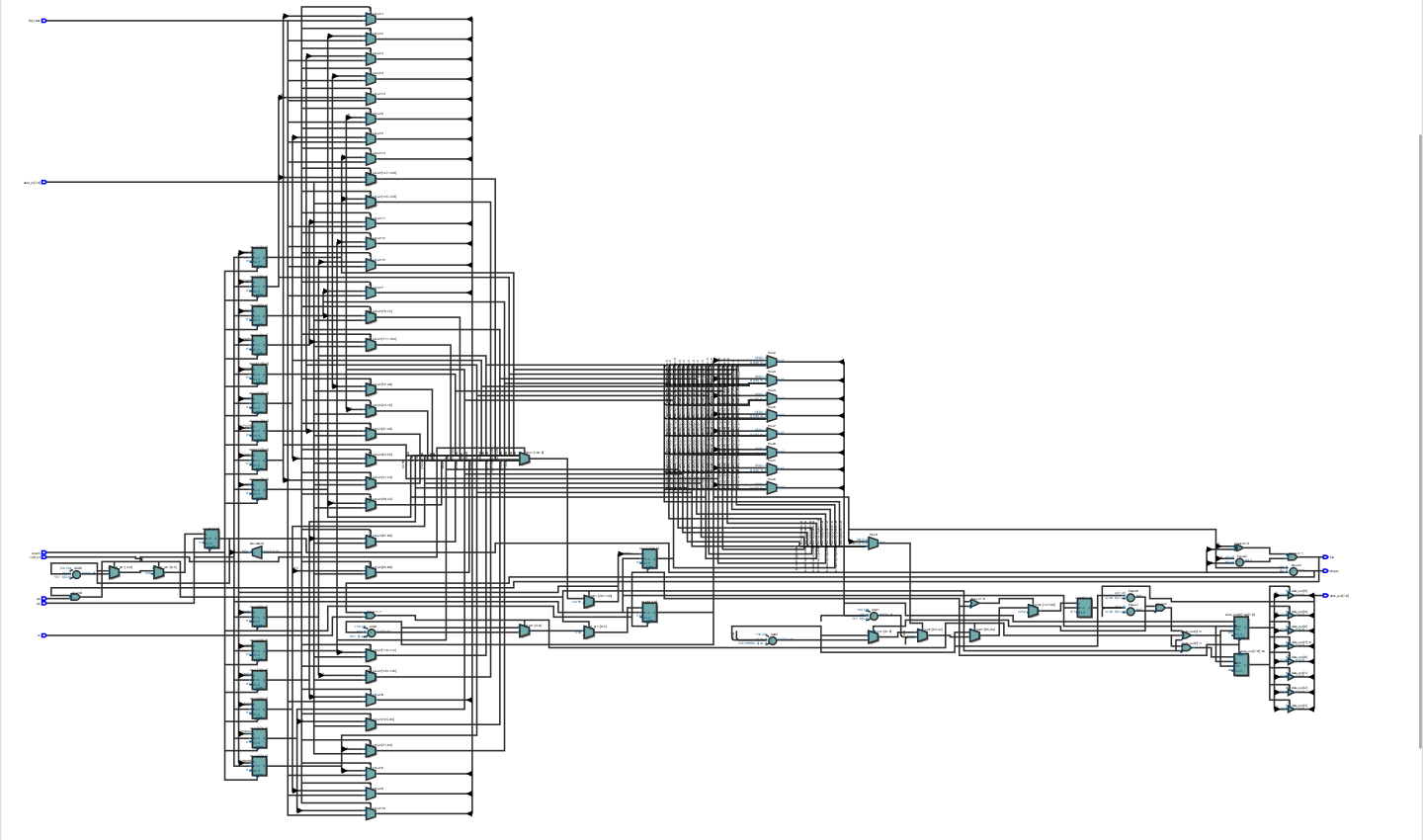
Block Diagram for FIFO
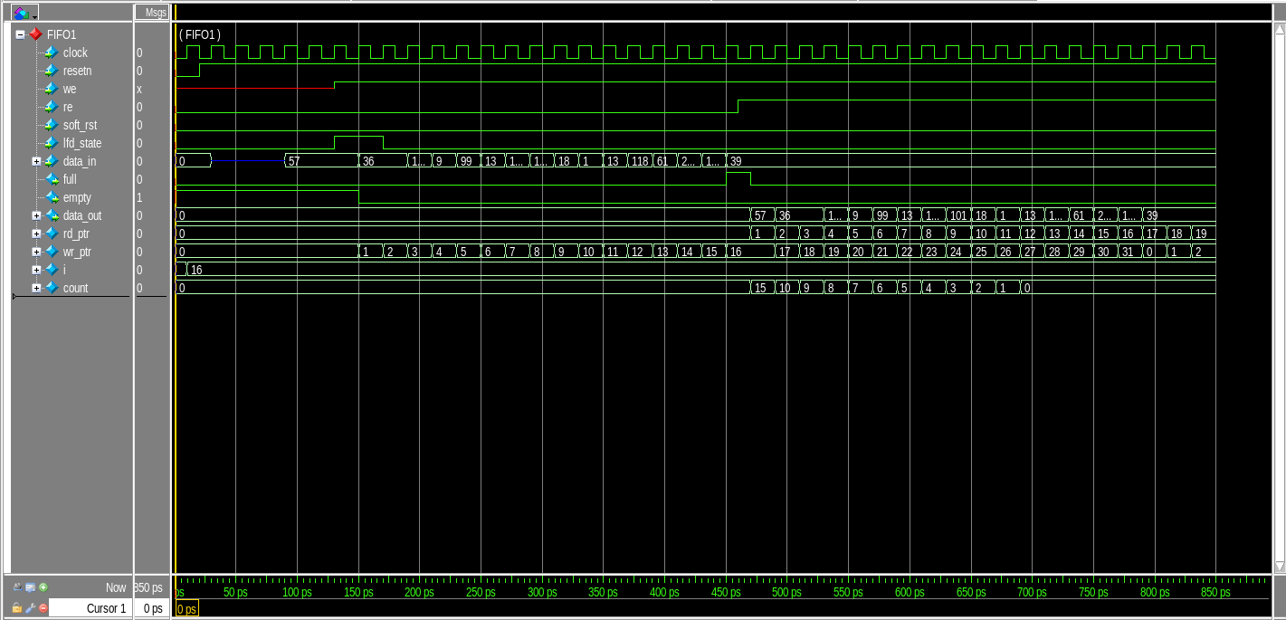
Timing Analysis for FIFO
Router Synchronizer
Ports for Synchronizer:
| Port | Type | Description |
|---|---|---|
| detect_add | input | used to select FIFO till a packet routing is over for the selected FIFO. |
| data_in | input | used to select FIFO till a packet routing is over for the selected FIFO. |
| we_reg | input | generate output write enable signal for the FIFO |
| clock | input | clock signal for the synchronizer |
| resetn | output | internal reset signal for the synchronizer |
| vld_out_0 | output | HIGH when ~empty_0 |
| vld_out_1 | output | HIGH when ~empty_1 |
| vld_out_2 | input | HIGH when ~empty_2 |
| re_0 | input | read enable signal for FIFO_0 |
| re_1 | input | read enable signal for FIFO_1 |
| re_2 | input | read enable signal for FIFO_2 |
| empty_0 | input | empty indicator for FIFO 0 |
| empty_1 | input | empty indicator for FIFO 1 |
| empty_2 | input | empty indicator for FIFO 2 |
| full_0 | output | full signal indication for FIFO_0 |
| full_1 | output | full signal indication for FIFO_1 |
| full_2 | output | full signal indication for FIFO_2 |
| fifo_full | output | equals to full_0 when data_in = 2’b00, full_1 when data_in = 2’b01, full_2 when data_in = 2’b10 else fifo_full =0. |
| soft_reset_0 | input | for FIFO 0. HIGH if re_0 is not asserted in 30 clock cycles of vld_out_0 being asserted. |
| soft_reset_1 | input | for FIFO 1. HIGH if re_2 is not asserted in 30 clock cycles of vld_out_1 being asserted. |
| soft_reset_2 | input | for FIFO 2. HIGH if re_2 is not asserted in 30 clock cycles of vld_out_2 being asserted. |
| write_enb | output | write enable signal for writing into FIFO |
: List of ports for the Router Synchronizer
Description:
This module provides synchronization between router FSM and router FIFO modules. It provides faithful communication between the single input port and three output ports.
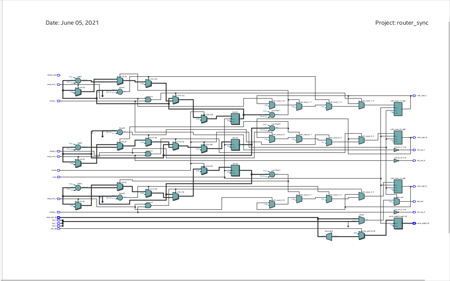
Block Diagram for Synchronizer
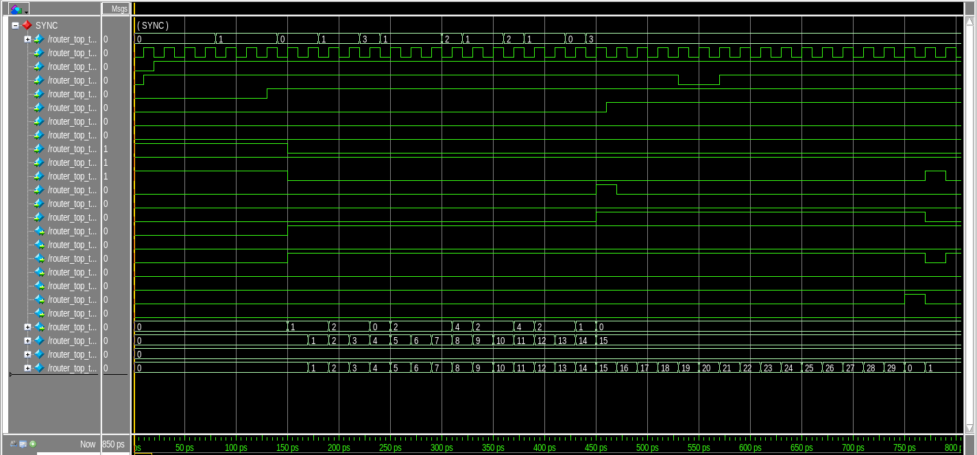
Timing Analysis for Synchronizer
Finite State Machine (FSM)
Description:
The FSM module is the controller circuit for the ROUTER. This module generates all the control signals when a new packet is received in order to transfer the packet to the output port.
Port Listing for Router FSM:
| Port | Type |
|---|---|
| data_in | input |
| clock | input |
| resetn | input |
| pkt_valid | input |
| parity_done | input |
| fifo_full | input |
| soft_reset_0 | input |
| soft_reset_1 | input |
| soft_reset_2 | input |
| low_pkt_valid | input |
| fifo_empty_0 | input |
| fifo_empty_1 | input |
| fifo_empty_2 | input |
| reg busy | output |
| write_enb_reg | output |
| reg detect_add | output |
| full_state | output |
| lfd_state | output |
| ld_state | output |
| laf_state | output |
| reg rst_int_reg | output |
: List of ports for Router FSM
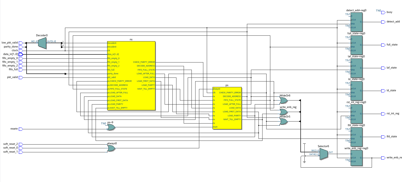
Block Diagram for Router FSM
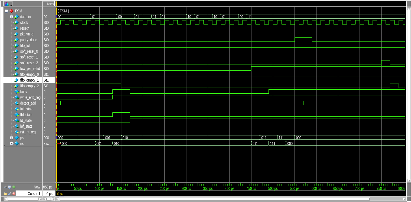
Timing Analysis for Router FSM
Register
Port Listing for Refister:
| Port | Type |
|---|---|
| clock | input |
| resetn | input |
| pkt_valid | input |
| data_in | input |
| fifo_full | input |
| rst_int_re | input |
| detect_add | input |
| full_state | input |
| ld_state | input |
| laf_state | input |
| lfd_state | input |
| parity_done | output |
| low_pkt_valid | output |
| err | output |
| dout | output |
List of ports for Router Register
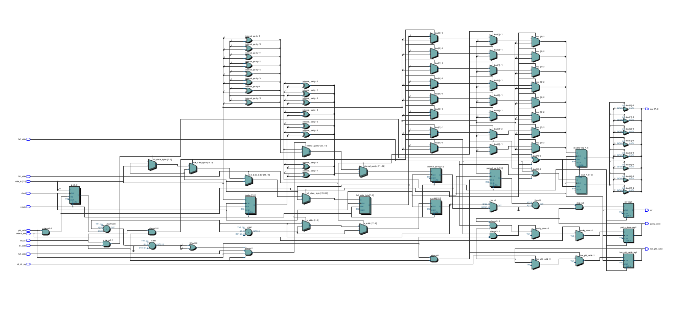
Block Diagram for Register
\newpage
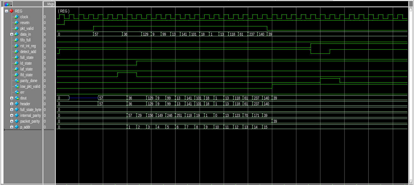
Timing Analysis for Register
Router Top
Port Listing for Router Top:
| Port | Type | Descriopion |
|---|---|---|
| clock | input | Clock signal |
| resetn | input | Active low reset |
| pkt_valid | input | Packet valid signal |
| data_in | input | 8-bit Input data |
| read_enbw | input | read enable pin |
| data_out0 | output | 8-bit data of FIFO-1 |
| data_out1 | output | 8-bit data of FIFO-2 |
| data_out2 | output | 8-bit data of FIFO-3 |
| busy | output | busy signal |
| err | output | error signal |
| vld_out_0 | output | valid out for FIFO-1 |
| vld_out_1 | output | valid out for FIFO-2 |
| vld_out_2 | output | valid out for FIFO-3 |
: List of ports for Router Top
Block Diagram for Router Top
Outputs:
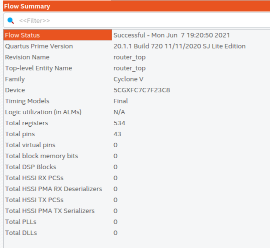
Flow Summary
\newpage
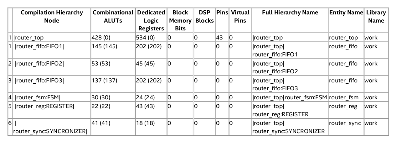
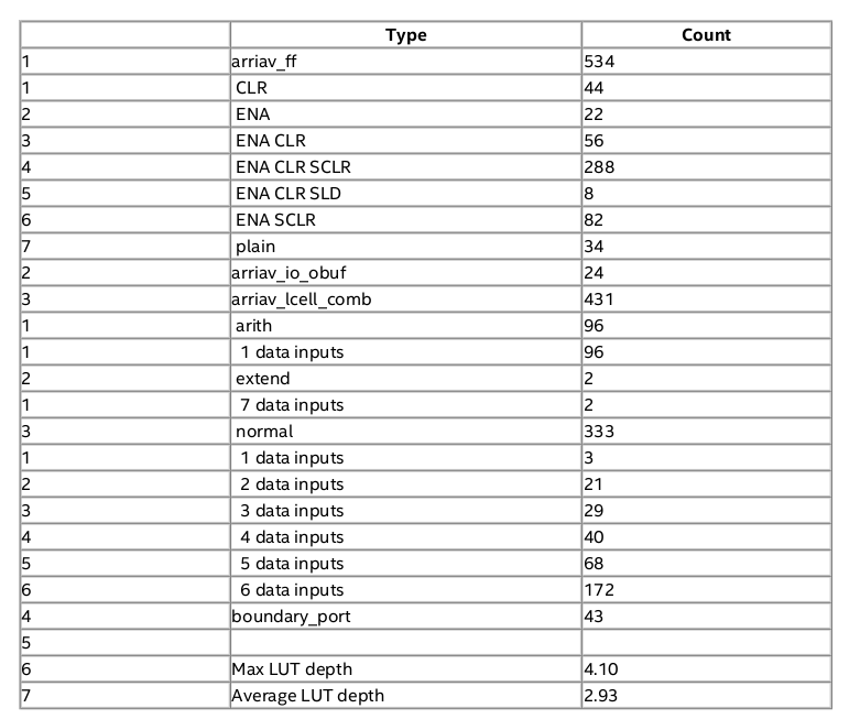
Analysis & Synthesis Resource Usage Summary:
\newpage
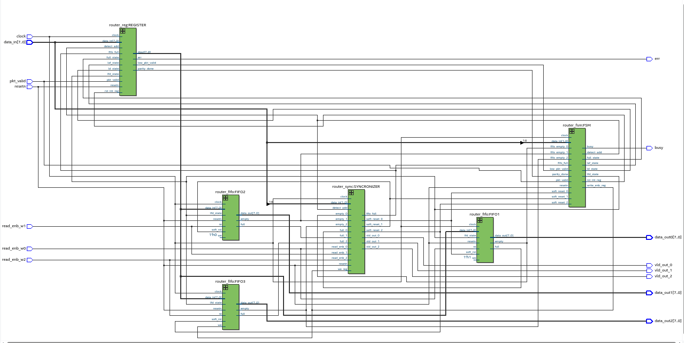
Post-Synthesis Netlist for Top Partition
\newpage
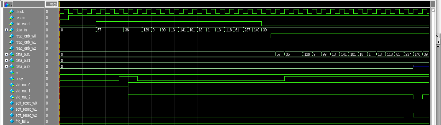
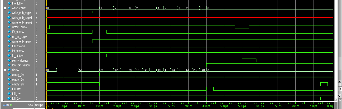
Timing Analysis for Router Top
- We shall be sending a data of 16 bytes and verify then receive it from FIFO-1. Also, I have disabled other two FIFO for this case.
- Router Top Timing Analysis
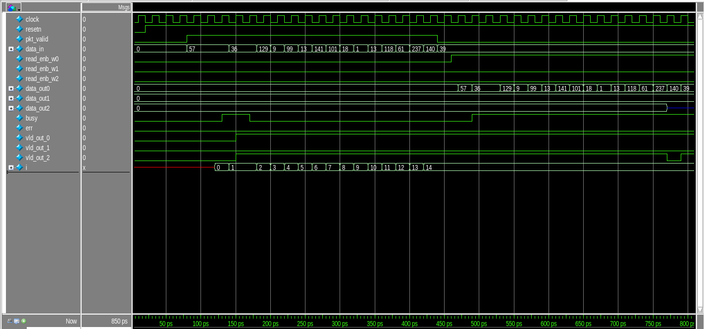
Router Top DUT
- We can see that FIFO-1 has faithfully reproduced the input data to the output.
Conclusion: The router is simulated and synthesized successfully.