Open Source Tools to Get Started With Verilog Simulation
Contents:
- Steps to Install Icarus Verilog and GTKWave
- How to edit and run the code with Icarus Verilog
- List of Programs
In this repo, I shall be using the open-source tools like iverilog for compiling the verilog code and gtk wave for observing timing diagrams.
Icarus verilog is a open-source verilog simulation and synthesis tool. It operates as a compiler, compiling source code written in Verilog (IEEE-1364) into some target format. For batch simulation, the compiler can generate an intermediate form called vvp assembly. This intermediate form is executed by the vvp command. For synthesis, the compiler generates netlists in the desired format. (visit Icarus Verilog for more information)
Steps to Install Icarus Verilog and GTKWave
Open the terminal and follow through the steps for the installtion of icarus verilog and gtkwave. Initially team-electronics package has to be added to the current packages. Do
sudo add-apt-repository ppa:team-electronics/ppa
You will get no message, which means the package has successfully added. Now update the local repository by
sudo apt-get update
Then install the Icarus verilog package
sudo apt-get install iverilog
and the gtkwave package which is used to view the timing diagrams for your verilog code.
sudo apt-get install gtkwave
How to edit and run the code with Icarus Verilog
Step-1: Write a verilog code
$ gedit hello1.v
Step-2: Compiling a verilog code with icarus verilog
$ iverilog hello1.v
Step-3: run the code
$ vvp a.out
List of Programs
- hello1.v
- inverter.v
- functions.v
- basic_gates.v
- Line Decoder
- 1 to 2 Line decoder
- 2 to 4 line decoder
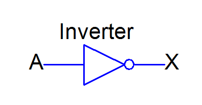
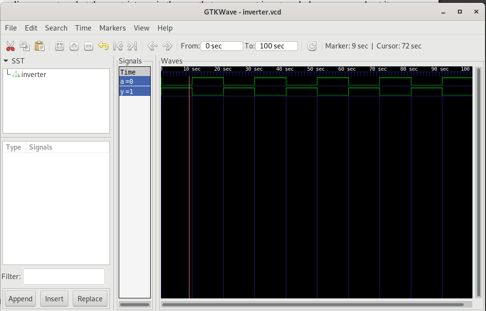
2. inverter
| Block diagram | Timing diagram |
|---|---|
 |
 |
| Inverter Code |
In digital logic, an inverter or NOT gate is a logic gate which implements logical negation.
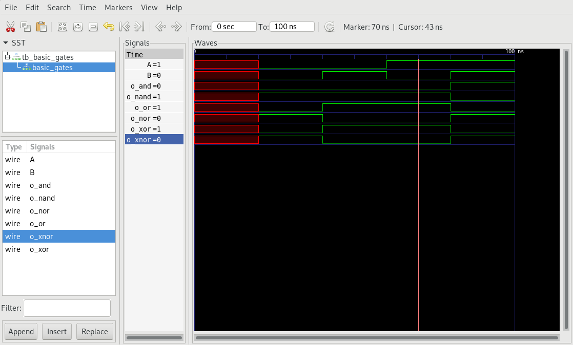
4. basic gates
| Schematic Diagram | Timing |
|---|---|
 |
 |
| Code |
- AND: Outputs HIGH when both inputs are HIGH.
- OR: Outputs LOW when both inputs are LOW.
- NAND: Outputs LOW when both inputs are HIGH.
- NOR: Outputs HIGH when both inputs are LOW.
- XOR: Outputs LOW when both the inputs are same.
- XNOR: Outputs HIGH when both inputs are same.
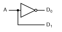
5. Line Decoder
- 1 to 2 Line decoder
- 2 to 4 line decoder
| 1 to 2 line decoder diagram | timing wave |
|---|---|
 |
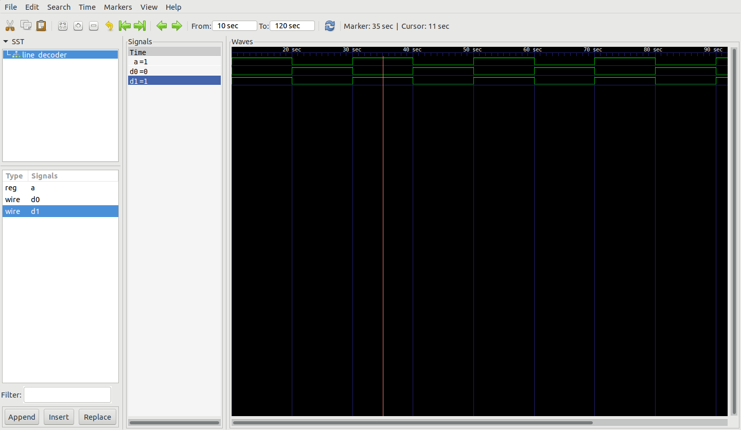 |
| 1 to 2 line decoder Code | |
| 2 to 4 line decoder | Timing wave |
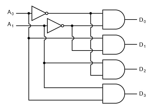 |
[timing] |
| 2 to 4 line decoder Code |