About_
Hi, I’m Karthik, a Digital Design Engineer with extensive professional experience in RTL design, formal verification, and hardware development. I completed my M.S. in Electrical and Computer Engineering from Purdue University, focused on building secure cryptographic hardware implementation in verilog.
My engineering journey began with hands-on experience in protocols like PCIe, I2C, UART, and AMBA, and evolved through developing IPs, writing synthesizable RTL, and performing lint, CDC, RDC, and power analysis. Whether I’m implementing CDC FIFOs or debugging formal runs, I approach each task with precision and a passion for clean, efficient design.
Achievements
- 1st Place, 600+ submissions in the “Circuit Design and Simulation Marathon using eSim” [June 2021]
- 5th Place out of 12 teams in the “IEEE HKN Founders Day Hackathon” [October 2024]
- Top 52 out of 400 finalists in the “Capture the Bug - A Design Verification Hackathon” [September 2022]
Workshops & Speaking
-
Speaker & Workshop Instructor, “Sand to Silicon: Build Your Custom ASICs”, Purdue University [March, April 2025]
Led a live session to design a stopwatch in Verilog and guided participants in deploying their programs on the Terasic DE10 Lite FPGA board. -
ECE Department Internship Instructor, Purdue University [January - May 2025]
Under the guidance of Dr. Lizhe Tan, led an internship for a small group of high school students, teaching them the basics of electronics, PCB design, and digital logic concepts. They successfully designed a traffic signal controller and a vending machine, standing out for their strong grasp of the material. -
PCB Design Workshop Instructor, Design Studio at Purdue University [March 29th, October 25th, 2024]
Conducted a hands-on workshop covering PCB fundamentals, including a live session on drawing schematics and trace routing using KiCad. Participants then soldered components onto their own PCB boards.
Feel free to explore my [portfolio](<!DOCTYPE html>
module Measuring Soil Moisture using Raspberry Pi ();
Do you know how often to water plants? Or outpoured plants and lost them. To solve this I thought it would be more circumstantial if we can get the value of water content inside the soil in order to make a decision for watering the plants appropriately.
In this project lets try to build a circuit which can measure the water content value of the soil eventually control the flow using Raspberry Pi.
Hardware:
- Raspberry Pi 2/3/4
- Soil moisture sensor
- MCP3008
- Jumpers
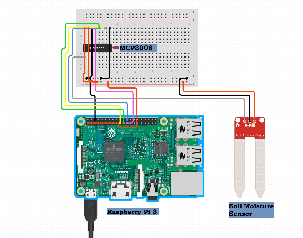
Circuit Connection:
- MCP3008 GND to GND
- MCP3008 CS to RPI 8
- MCP3008 DIN to RPI 10
- MCP3008 DOUT to RPI 9
- MCP3008 CLK to RPI 11
- MCP3008 AGND to GND
- MCP3008 VREF to +3V
- MCP3008 VCC to +3V
- SoilMoisture A0 to MCP3008 CH0
- SoilMoisture VCC to +3V
- SoilMoisture GND to GND
Make all the connections and power up the Raspberry Pi. If you want to learn how to connect a Raspberry Pi check out my previous post on how to Set Up Raspberry Pi 4 Through Laptop/pc Using Ethernet Cable(No Monitor, No Wi-Fi)
Essential Packages
Before you run the code you have to install few libraries, move on with the following steps.
sudo apt-get update
sudo apt-get install build-essential python-dev python-smbus git
cd ~
git clone https://github.com/adafruit/Adafruit_Python_MCP3008.git
cd Adafruit_Python_MCP3008
[sudo](sudo) python setup.py install
The Code
Once the library has been installed it’s time to execute the code. You can use the below code or download it from here1.
import RPi.GPIO as GPIO
from time import sleep

import Adafruit_MCP3008

am = Adafruit_MCP3008.MCP3008(clk = 11, cs = 8, miso = 9, mosi = 10)

while True:
  moisture_value = am.read_adc(0)
  per = moisture_value * 100 / 1023
  print("Recorded moisture value is %s percentage" % per)
  if moisture_value >= 930:
    print(" No water, Can you plaease water me")
  elif moisture_value < 930 and moisture_value >= 350:
    print(" I'm sufficient ")
  elif moisture_value < 350 :
    print(" Stop drowning me!")
  sleep(1.5)
Youtube Video Tutorial:
You can rewrite the code and change the parameters for your requirements. If you have suggestions or any trouble with the project, feel free to comment below. Happy Circuiting!
>> User_Feedback_Loop
<!DOCTYPE html>
module Set Up Raspberry Pi 4 through laptop/pc using Ethernet cable(No Monitor, No Wi-Fi) ();
Contents
In this we shall be working with Raspberry Pi 4 Model-B of 1Gb RAM for the set up. Raspberry-Pi is a single board computer used for educational purposes and DIY projects with an affordable cost, requires a power supply of 5 volts with 3 amps current.
Operating Systems like Raspbian OS, Windows, Linux, RISC OS, can be installed into it. The Pi 4 model has Ethernet, wireless adapter, USB type-C port, and 40 GPIO(General Purpose Input Output) pins. Unlike the older versions the performance has very much improved with the “Pi 4” model.
Hardware Requirements:
- Raspberry Pi 4 Model B (1/2/4 GB RAM)
- USB Type-C power supply
- Ethernet cable (1 meter)
- Personal computer
Steps to install the required software tools
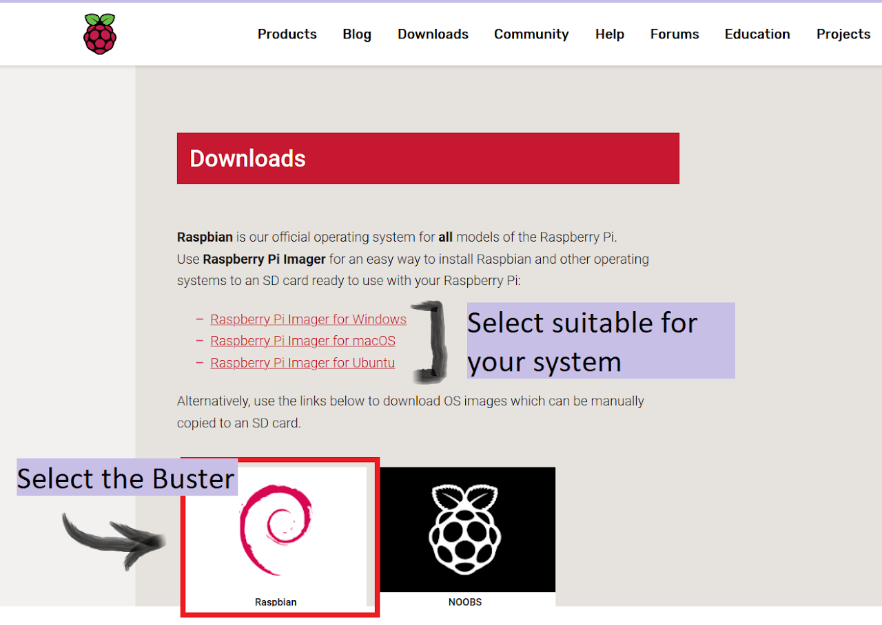
Step-1: OS Download
From the official raspberrypi.org1 download the Raspbian Buster operating system
Step-2: Imager
Also download the Raspberry Pi Imager2 from the same website, this is for writing the image file onto the SD card.
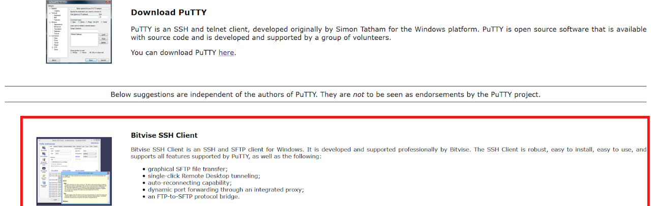
Step-3: SSH Client Download
If you are using windows you probably have to download the ssh client, I prefer downloading Bitvise ssh client from PuTTY3.
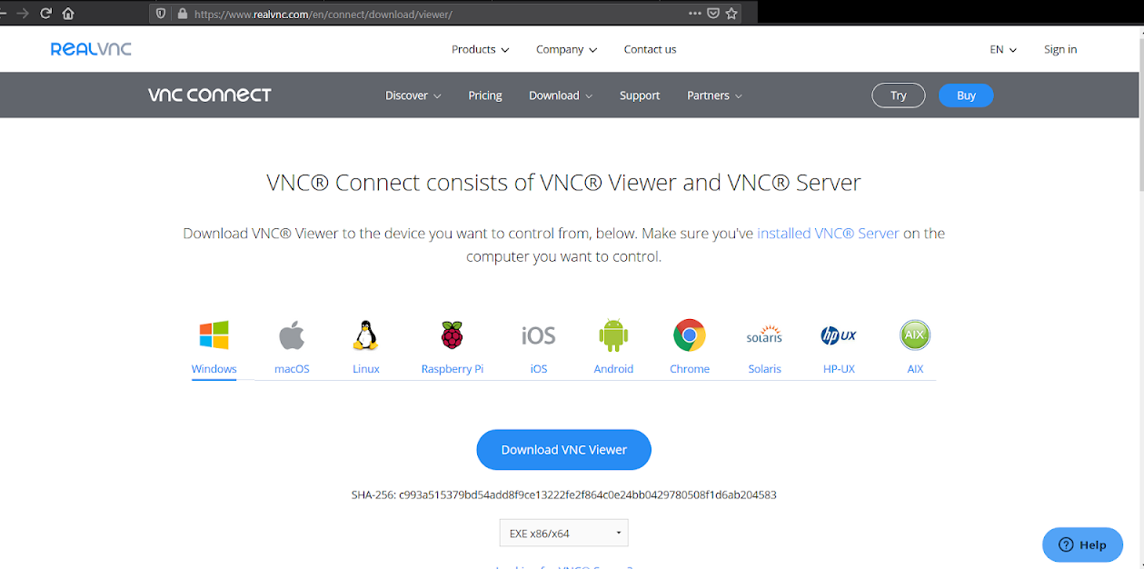
Step-4: Real VNC Viewer
To access the desktop of the pi, you can either connect a micro to HDMI connector from the pi to a monitor or you can access it remotely on your PC/laptop. To connect remotely VNC-server has to be installed onto the pi by default the VNC-server is installed within the operating system, in order to view it remotely one has to download VNC-Viewer4 on his/her Desktop.
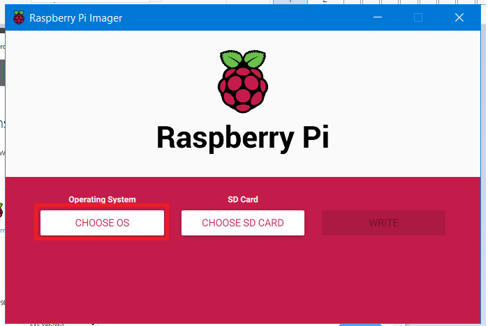
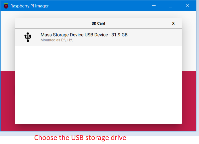
Step-5: Image Burning
Open the Raspberry Pi Imager and select the custom setup then select the OS from the Downloaded folder and carefully set the target as USB drive. Wait for the image to be written on the drive.
 |
 |
 |
|---|---|---|
| 1 | 2 | 3 |
 |
 |
|---|---|
| 4 | 5 |
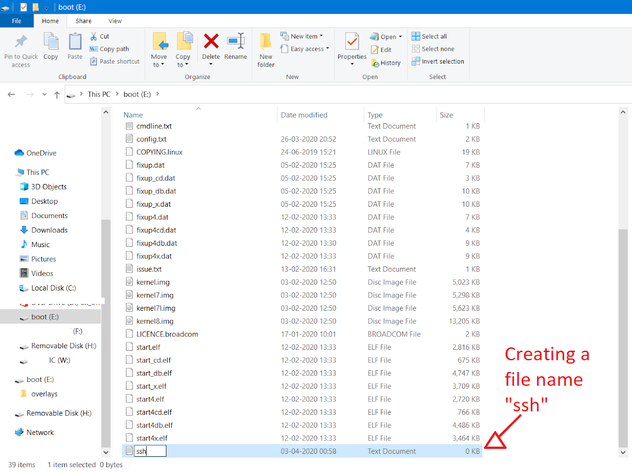
Step-6: ssh
After done, open the boot folder, create a new document named ssh without any extensions, save and then unmount the drive.
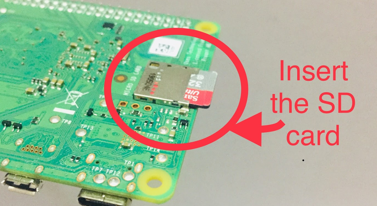
Step-7: Power
Now connect the Ethernet cable to your PC/lap and power up the pi with the type-C cable.
 |
|  |
|  — | — | —
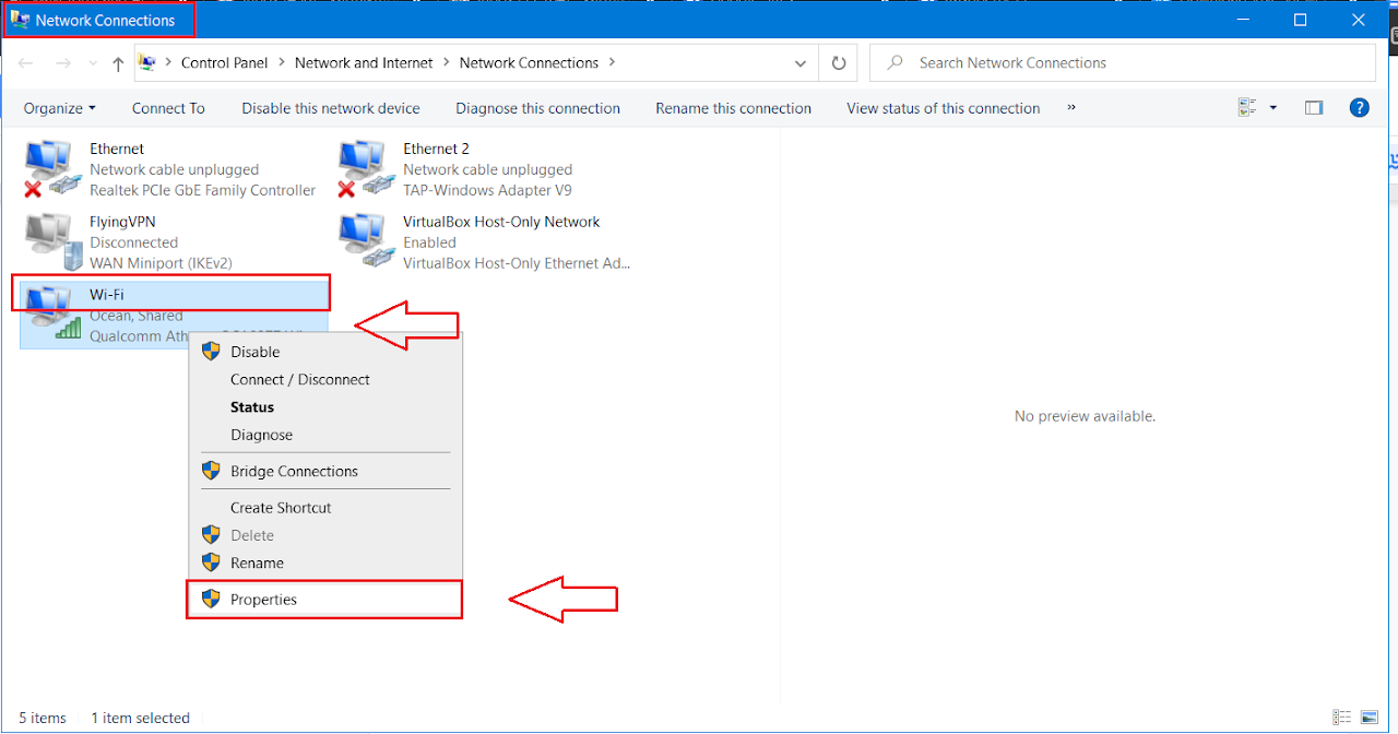
Step-8: Network Connections
If you are using Windows 10 go to Control Panel –> Network and Internet –> Network Connections, right-click on Wi-Fi select properties, go to sharing section and check on “Allow other network users to connect through this computer’s Internet connection”. Make sure that Home network connection is Ethernet. Save and close the window.
 |
|  — | —
— | —
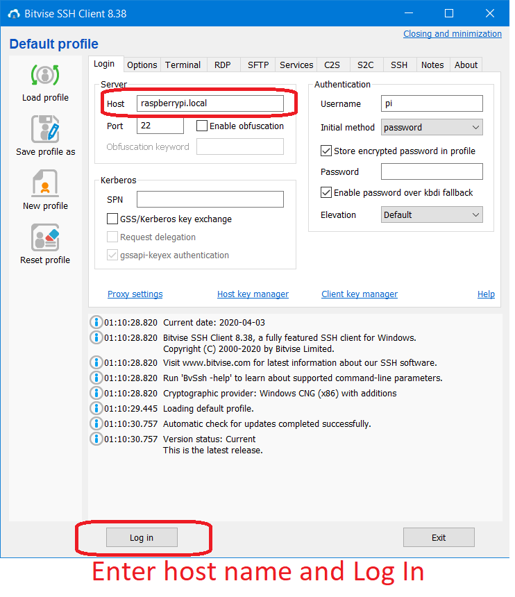
Step-9: SSH Configuration
Open the Bitvise SSH Client, enter raspberrypi.local or the IP address(from previous step) as host and leave 22 as default port in the server section.
Step-10: Authentication
Click Log in and enter username as pi and the default password as raspberry. A terminal pops up and you are now into the Raspberry Pi.
 |
|  — | —
— | —
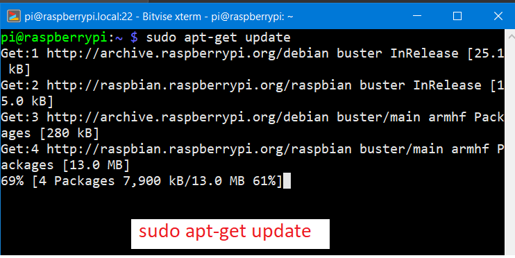
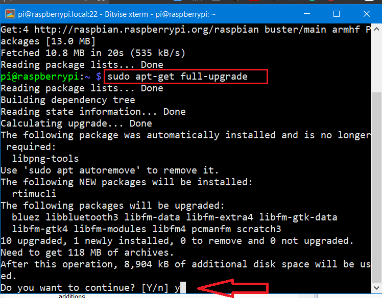
Step-11: Pi Terminal
If this is your first time logging into pi make sure to update your pi by issuing the command sudo apt-get update and then sudo apt-get upgrade to upgrade.
Quick tip: Don’t forget to change your password once you are log in.
Accessing Pi Desktop Remotely
- Go to terminal and type
vncserver, notedown the generated ip address. Now open VNC-Viewer on your desktop and enter the ip addressor paste it, after few seconds a window pops sharing the screen of raspberry pi.
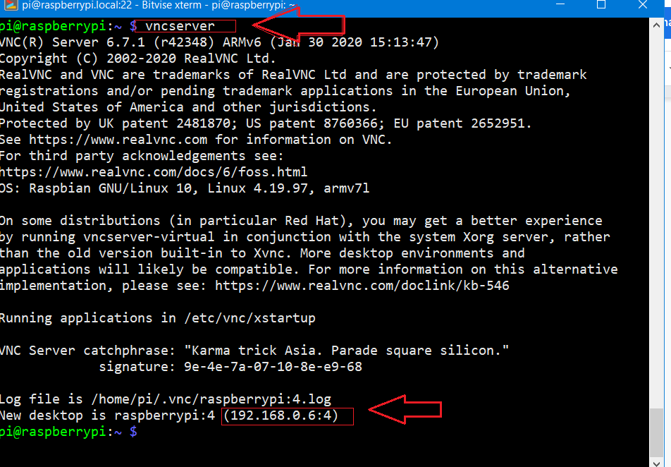
- Enter the ip address given by
vncserverfrom the raspberry pi to vncviewer application on your pc.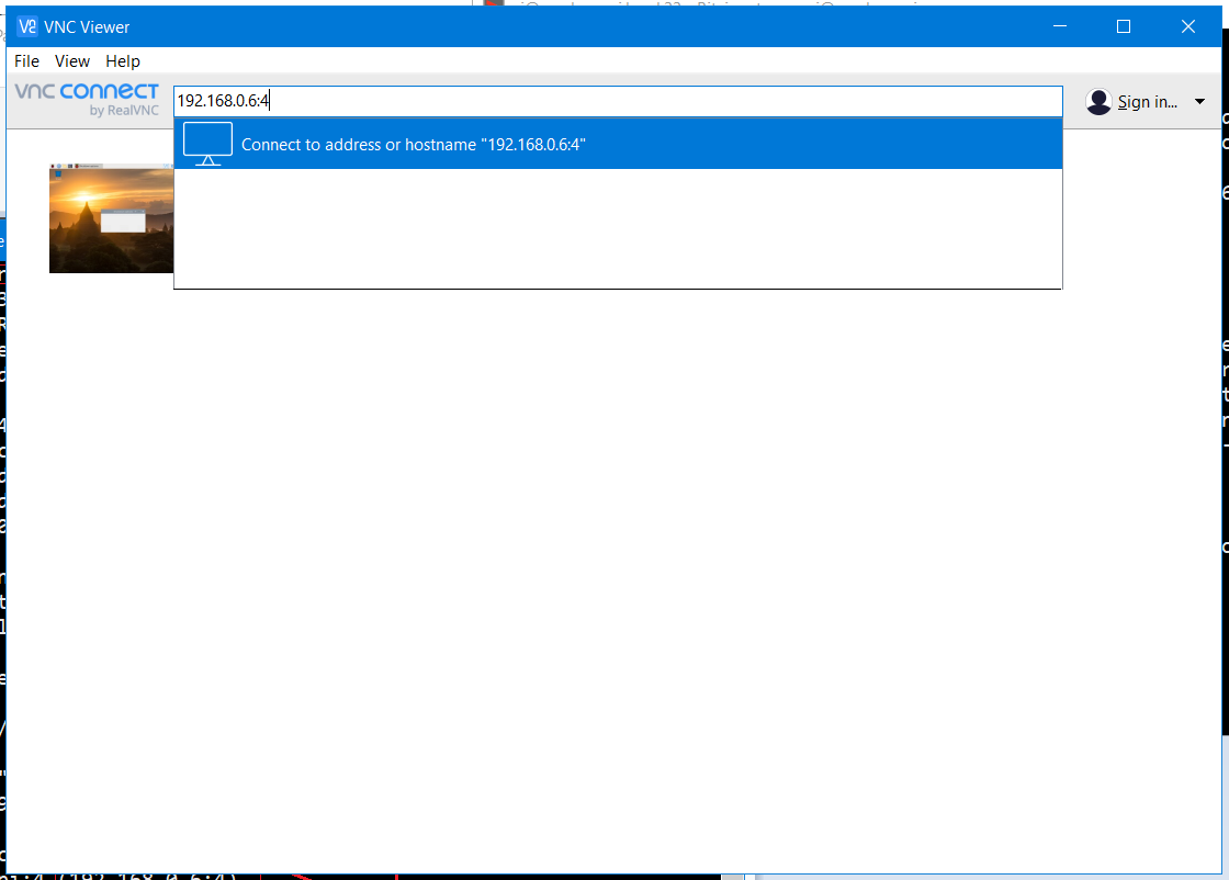
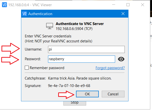
Enter the username and password on the authentication prompt.
-
Welcome! to Pi’s desktop.

-
This article was originally published in instructables website5.
References:
-
https://www.raspberrypi.org/software/ ↩
-
Set Up Raspberry Pi 4 Through Laptop/pc Using Ethernet Cable(No Monitor, No Wi-Fi) ↩
>> User_Feedback_Loop
<!DOCTYPE html>
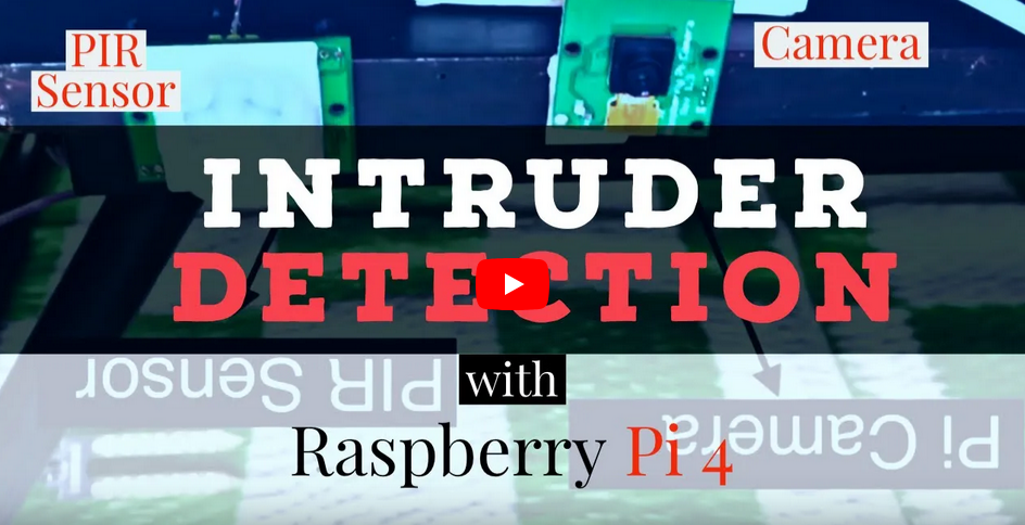
module Intruder Detection Using Pi Camera ();
Contents
This project is about capturing the pictures of strangers through the Pi Camera attached to Raspberry Pi. This is a DIY project which can detect people using the motion sensor(PIR sensor) by capturing a photo whenever the motion is detected.
Hardware
- Raspberry Pi 2/3/4
- Pi Camera
- PIR Sensor
- Jumpers
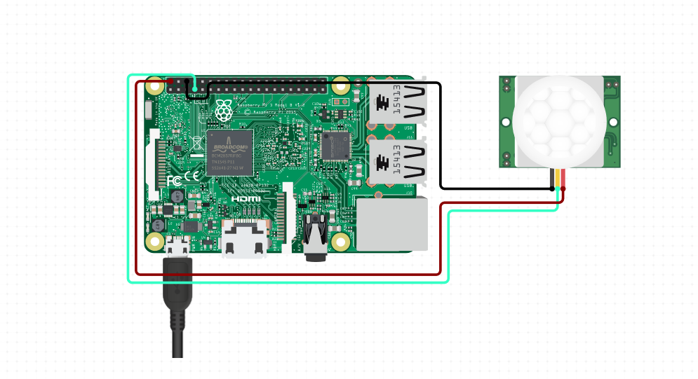
Circuit Connection

Connect the PIR sensor to raspberry pi as shown in the above circuit diagram. Additionally connect the Pi Cam to Raspberry Pi camera port. To check whether your camera is working or not run the following code.
raspistill -o Desktop/image.jpg
Apparantly, you should see the image saved on your Desktop, if not make sure you connected the camera properly and restart the device.
The Code
Save the below code as pir-camera-test.py and run.
   #Code for Capturing Strangers:

   from gpiozero import MotionSensor
   from picamera import PiCamera
   import RPi.GPIO as GPIO
   import time

   GPIO.setmode(GPIO.BCM)
   GPIO.setwarnings(False)

   pir=MotionSensor(23)
   camera=PiCamera()
   camera.rotation = 180
   camera.start_preview()

   while True:
    GPIO.setup(24, GPIO.OUT)
    if pir.wait_for_motion():
        GPIO.output(24, GPIO.HIGH)
        #time.sleep(0.1)
        print("Motion Detected")
        camera.capture('/home/pi/Marvel/PiCam/PiImage/Strangers/image-'+ time.ctime()+'.png')
         print("image-"+time.ctime())
         GPIO.output(24, GPIO.LOW)

    else:
        print("Motion not Detected")
    time.sleep(3)
   camera.stop_preview()
   camera.close()
Youtube Video Tutorial:
You can rewrite the code and change the parameters for your requirements. If you have suggestions or any trouble with the project, feel free to comment below. Happy Circuiting!
-
https://youtu.be/Nw-yHMn69R0?t=47 ↩
>> User_Feedback_Loop
<!DOCTYPE html>
module Set up Raspberry Pi 4(Wi-Fi) ();

Contents
The set up for Raspberry Pi using Wi-Fi is the same as the previous article on how to Set Up Raspberry Pi 4 through laptop/pc using Ethernet cable(No Moniter, No Wi-Fi) with some minor changes which we are going to see.
Hardware Requirements:
- Raspberry Pi 4 Model B (1/2/4 GB RAM)
- USB Type-C power supply
- Personal computer
Steps to install the required software tools
- If you had followed the previous article then skip these steps and move to ‘step-6’. From the official raspberrypi.org download the Raspbian Buster operating system1
- Also, download the Raspberry Pi Imager from the website2, this is for writing the image file onto the SD card.
- If you are using windows you probably have to download the ssh client, I prefer downloading it from Bitvise ssh client from PuTTY.
Further Steps:
-
To access the desktop of the pi, you can either connect a micro to HDMI connector from the pi to a monitor or you can access it remotely on your PC/laptop. To connect remotely VNC-server has to be installed onto the pi by default the VNC-server is installed within the operating system, in order to view it remotely one has to download VNC-viewer on his/her Desktop.
-
Open the Raspberry Pi Imager and select the custom setup then select the OS from the Downloaded folder and carefully set the target as a USB drive. Wait for the image to be written on the card.
-
After done, open the boot folder, create a new document named “ssh” without any extensions. Create another text file, enter the following configurations and save it as
wpa_supplicant.conf. Dont forget to enter the country code and the wi-fi credentials.
ctrl_interface=DIR=/var/run/wpa_supplicant GROUP=netdev
update_config=1
country=<Insert country code here>

network={

    ssid="testing"
    psk="testingPassword"

}
-
Now power up the pi with the type-C cable and wait for a while for the pi to be connect to your Wi-Fi.
-
Open Advanced IP Scanner and make a quick scan, identify the Raspberry Pi and note the IP address.
-
Open the Bitvise SSH Client3, enter
raspberrypi.localor the IP address(from the previous step) as host and leave 22 as default port in the server section.
-
Click Log in and enter the username as pi and the default password as raspberry. A terminal pops up and you are now into the Raspberry Pi.
-
If this is your first time logging into pi make sure to update your pi by issuing the command
sudo apt-get updateand thensudo apt-get upgradeto upgrade.
$ sudo apt-get update
$ sudo apt-get upgrade
Quick tip: Don’t forget to change your password once you are logged in.
Accessing Pi Desktop Remotely
- Go to terminal and type
vncserver, notedown the generated ip address. Now open VNC-Viewer4 on your desktop and enter the ip address or paste it, after few seconds a window pops sharing the screen of raspberry pi desktop.
>> User_Feedback_Loop
<!DOCTYPE html>
module Open Source Tools to Get Started With Verilog Simulation ();
Contents:
- Steps to Install Icarus Verilog and GTKWave
- How to edit and run the code with Icarus Verilog
- List of Programs
In this repo, I shall be using the open-source tools like iverilog for compiling the verilog code and gtk wave for observing timing diagrams.
Icarus verilog is a open-source verilog simulation and synthesis tool. It operates as a compiler, compiling source code written in Verilog (IEEE-1364) into some target format. For batch simulation, the compiler can generate an intermediate form called vvp assembly. This intermediate form is executed by the vvp command. For synthesis, the compiler generates netlists in the desired format. (visit Icarus Verilog for more information)
Steps to Install Icarus Verilog and GTKWave
Open the terminal and follow through the steps for the installtion of icarus verilog and gtkwave. Initially team-electronics package has to be added to the current packages. Do
sudo add-apt-repository ppa:team-electronics/ppa
You will get no message, which means the package has successfully added. Now update the local repository by
sudo apt-get update
Then install the Icarus verilog package
sudo apt-get install iverilog
and the gtkwave package which is used to view the timing diagrams for your verilog code.
sudo apt-get install gtkwave
How to edit and run the code with Icarus Verilog
Step-1: Write a verilog code
$ gedit hello1.v
Step-2: Compiling a verilog code with icarus verilog
$ iverilog hello1.v
Step-3: run the code
$ vvp a.out
List of Programs
- hello1.v
- inverter.v
- functions.v
- basic_gates.v
- Line Decoder
- 1 to 2 Line decoder
- 2 to 4 line decoder
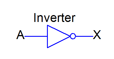
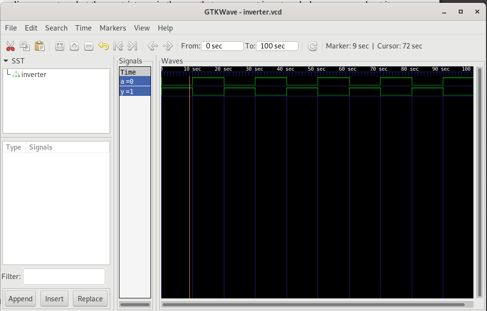
2. inverter
| Block diagram | Timing diagram |
|---|---|
 |
 |
| Inverter Code |
In digital logic, an inverter or NOT gate is a logic gate which implements logical negation.
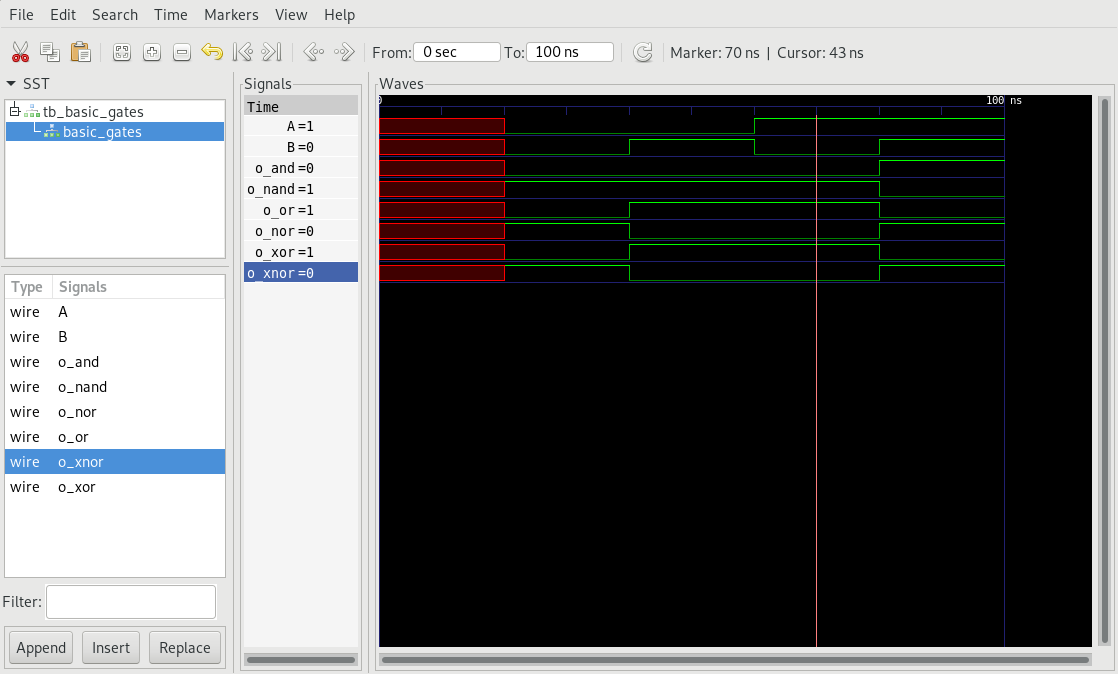
4. basic gates
| Schematic Diagram | Timing |
|---|---|
 |
 |
| Code |
- AND: Outputs HIGH when both inputs are HIGH.
- OR: Outputs LOW when both inputs are LOW.
- NAND: Outputs LOW when both inputs are HIGH.
- NOR: Outputs HIGH when both inputs are LOW.
- XOR: Outputs LOW when both the inputs are same.
- XNOR: Outputs HIGH when both inputs are same.
5. Line Decoder
- 1 to 2 Line decoder
- 2 to 4 line decoder
| 1 to 2 line decoder diagram | timing wave |
|---|---|
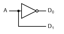 |
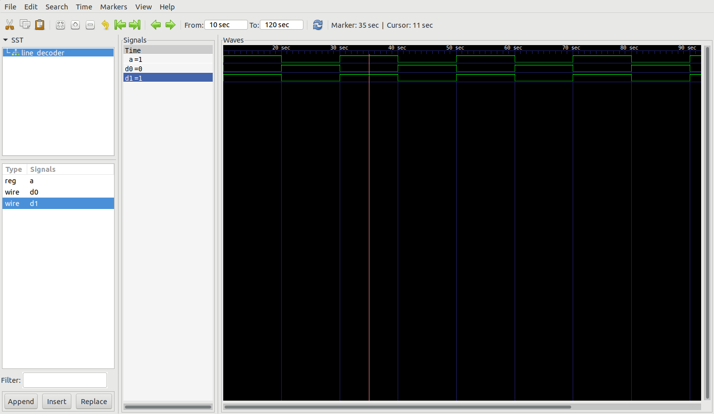 |
| 1 to 2 line decoder Code | |
| 2 to 4 line decoder | Timing wave |
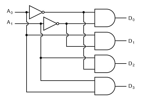 |
[timing] |
| 2 to 4 line decoder Code |
>> User_Feedback_Loop
<!DOCTYPE html>
module Making Custom Siri Shortcuts with Block Programming ();
Apple has this amazing feature where you can block code to perform tasks that can convert markdown to rich text or extract source code from a html page or drain water from your iphone. Your can dowload Shortcuts from App store1. Here are my custom siri shortcuts, hope you like them.
1) Markdown to Rich text
- Input any text to this shortcut, which will be rendered to text and save it as pdf.
Shortcut Link | Markdown to Rich text — | —
2) Okay
- Input your favourite text and siri will read it for you.
Shortcut Link | Okay — | —
3) RightLeft
- Have you ever went on a random ride? Here you can input maximum turns to be taken, you will be displayed a turn to make and once you take the turn click okay for NEXT turn and it continues till the end.

Shortcut Link | RightLeft — | —
4) Instagram Grid
- convert the 16:9, panorama images into Instagram squares.
Shortcut Link | Instagram Grid — | —
5) Photo College
- Select a group of images to combine them into a college.
Shortcut Link | Photo College — | —
6) Network Details
- This is a simple tool for getting the details of your network. Choose from the below options to start with
- Wi-Fi
- Cellular

Shortcut Link | Network Details — | —
7) Blink-Limus
- blink your iPhone’s flashlight
Shortcut Link | Blink-Limus — | —
8) Ciffer Tekst
- Encrypt any text and then use the encrypted text to decrypt it
Shortcut Link | Ciffer Tekst — | —
Post on recommended siri shortcuts coming soon.
-
https://apps.apple.com/us/app/shortcuts/id915249334 ↩
>> User_Feedback_Loop
<!DOCTYPE html>
module Design and Verification of a 3 Port Router in Verilog ();

A router is a networking device that forwards data packets between computer networks. Routers perform the traffic directing functions on the Internet. Data sent through the internet, such as a web page or email, is in the form of data packets. A packet is typically forwarded from one router to another router through the networks that constitute an internetwork (e.g. the Internet) until it reaches its destination node.1
First IN First OUT
Description
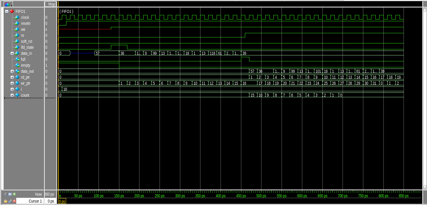
- In this FIFO is of length 9-bits width and 16 locations of depth, means the FIFO has a memory size of 16x9. The FIFO works on the system clock and is reset from synchronous active LOW reset.
Port listing of FIFO:
| Port | Type | Description |
|---|---|---|
| clock | input | clock signal |
| resetn | input | active-low reset pin |
| we | input | write enable pin |
| re | input | read enable pin |
| soft_rst | input | soft reset |
| lfd_state | input | active high on load first data |
| data_in | input | 8-bit input data |
| full | output | High when data is written into FIFO register |
| empty | output | High when FIFO register is empty |
| data_out | output | 8-bit output data |
List of ports for Router FIFO
Block Diagram for FIFO
Timing Analysis for FIFO
Router Synchronizer
Ports for Synchronizer:
| Port | Type | Description |
|---|---|---|
| detect_add | input | used to select FIFO till a packet routing is over for the selected FIFO. |
| data_in | input | used to select FIFO till a packet routing is over for the selected FIFO. |
| we_reg | input | generate output write enable signal for the FIFO |
| clock | input | clock signal for the synchronizer |
| resetn | output | internal reset signal for the synchronizer |
| vld_out_0 | output | HIGH when ~empty_0 |
| vld_out_1 | output | HIGH when ~empty_1 |
| vld_out_2 | input | HIGH when ~empty_2 |
| re_0 | input | read enable signal for FIFO_0 |
| re_1 | input | read enable signal for FIFO_1 |
| re_2 | input | read enable signal for FIFO_2 |
| empty_0 | input | empty indicator for FIFO 0 |
| empty_1 | input | empty indicator for FIFO 1 |
| empty_2 | input | empty indicator for FIFO 2 |
| full_0 | output | full signal indication for FIFO_0 |
| full_1 | output | full signal indication for FIFO_1 |
| full_2 | output | full signal indication for FIFO_2 |
| fifo_full | output | equals to full_0 when data_in = 2’b00, full_1 when data_in = 2’b01, full_2 when data_in = 2’b10 else fifo_full =0. |
| soft_reset_0 | input | for FIFO 0. HIGH if re_0 is not asserted in 30 clock cycles of vld_out_0 being asserted. |
| soft_reset_1 | input | for FIFO 1. HIGH if re_2 is not asserted in 30 clock cycles of vld_out_1 being asserted. |
| soft_reset_2 | input | for FIFO 2. HIGH if re_2 is not asserted in 30 clock cycles of vld_out_2 being asserted. |
| write_enb | output | write enable signal for writing into FIFO |
: List of ports for the Router Synchronizer
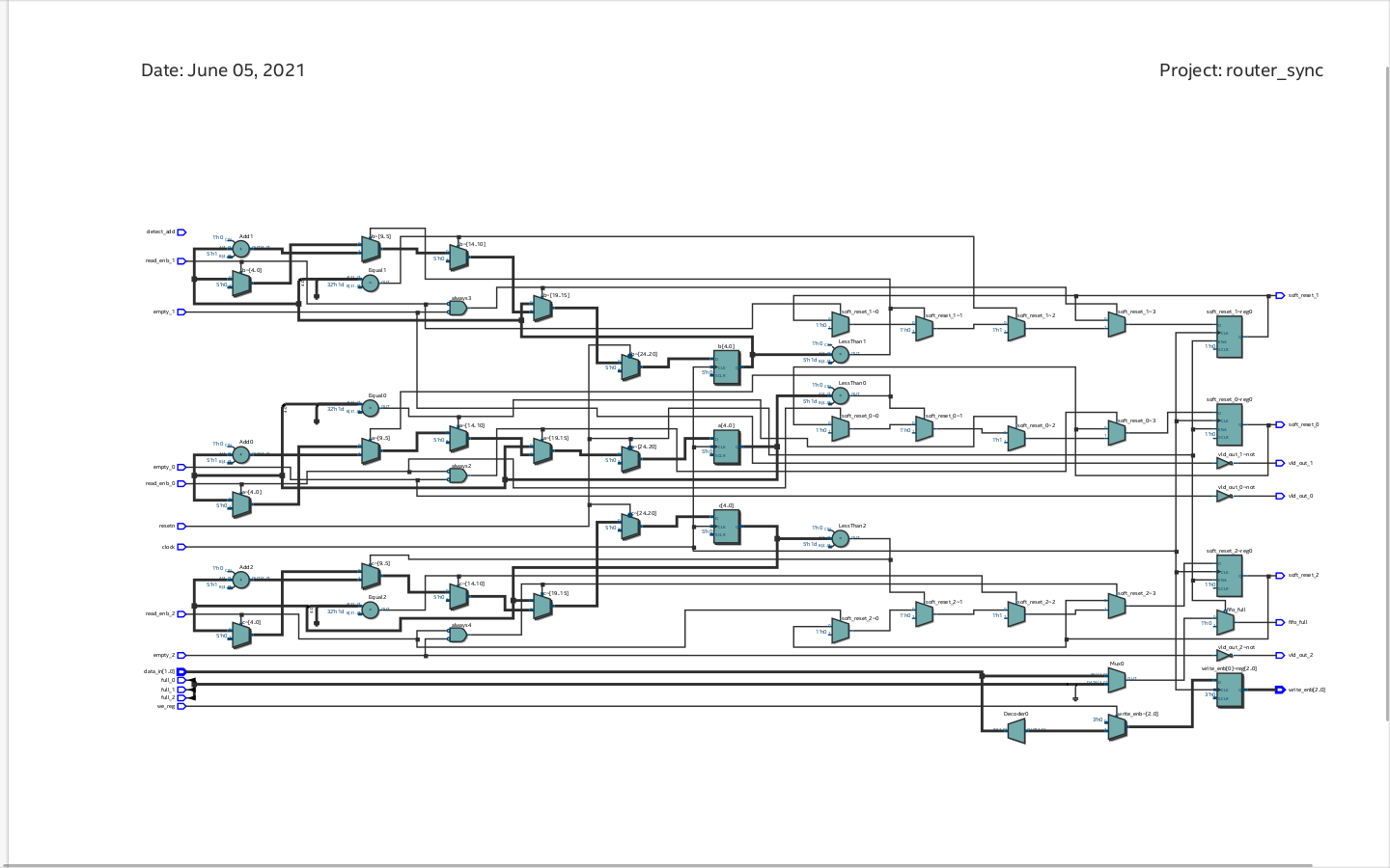
Description:
This module provides synchronization between router FSM and router FIFO modules. It provides faithful communication between the single input port and three output ports.
Block Diagram for Synchronizer
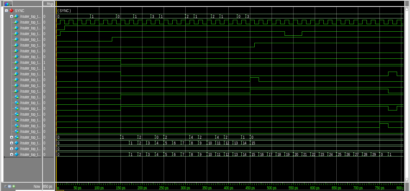
Timing Analysis for Synchronizer
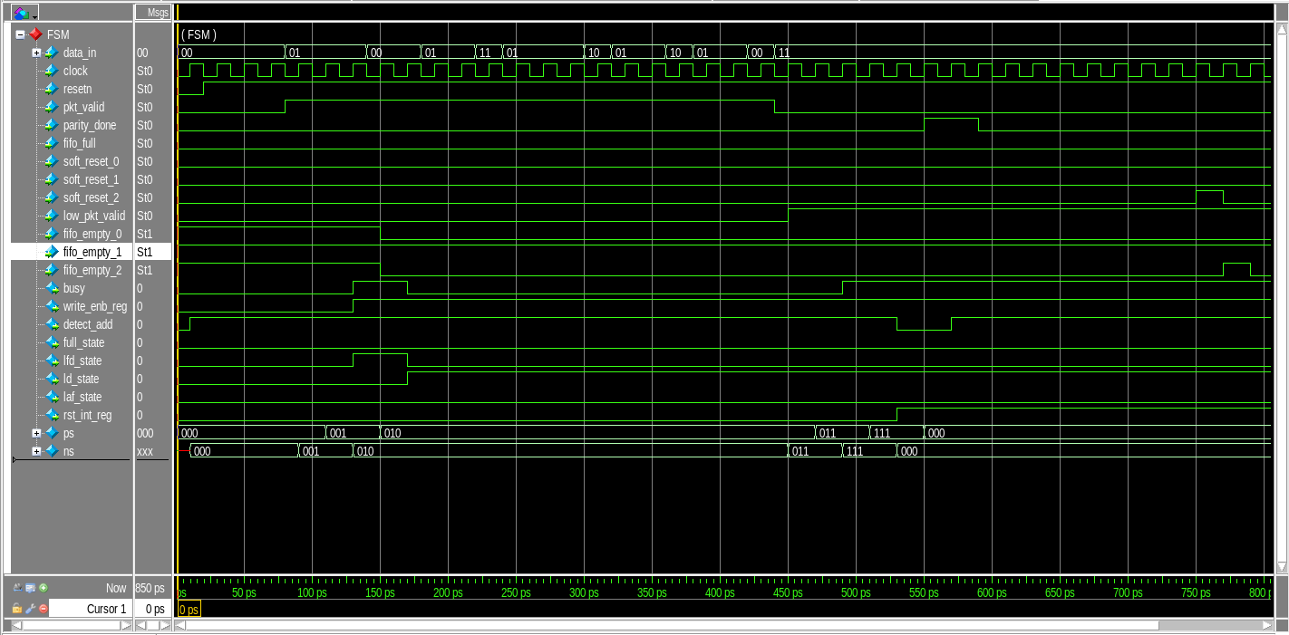
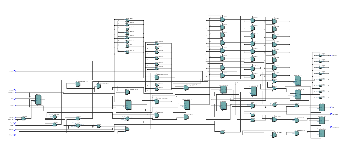
Finite State Machine (FSM)
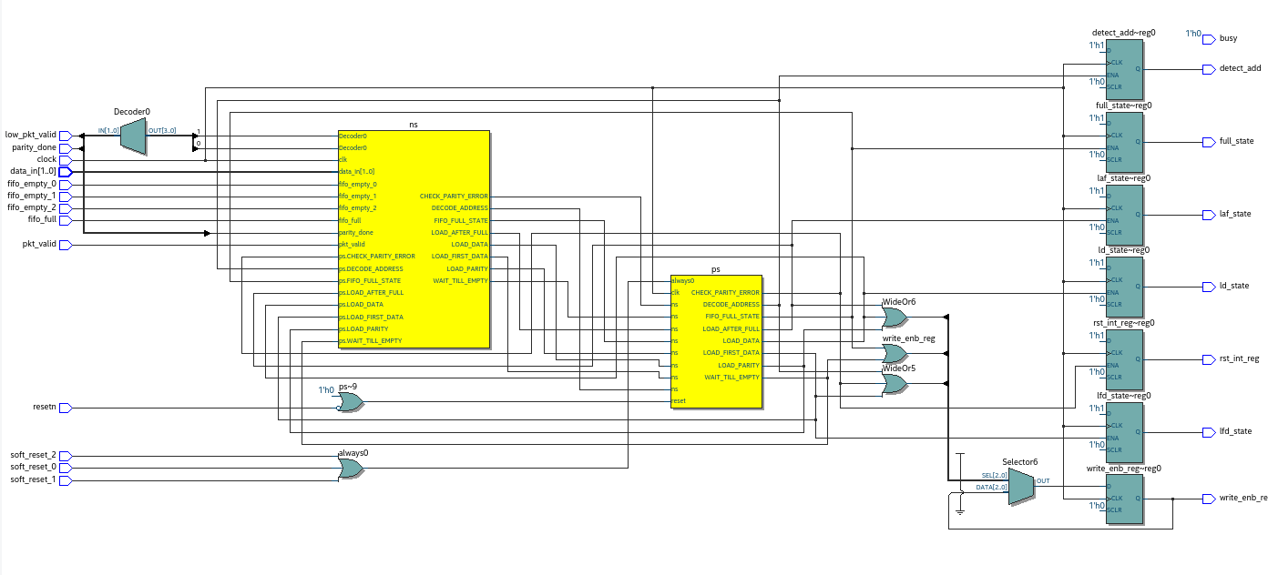
Description:
The FSM module is the controller circuit for the ROUTER. This module generates all the control signals when a new packet is received in order to transfer the packet to the output port.
Port Listing for Router FSM:
| Port | Type |
|---|---|
| data_in | input |
| clock | input |
| resetn | input |
| pkt_valid | input |
| parity_done | input |
| fifo_full | input |
| soft_reset_0 | input |
| soft_reset_1 | input |
| soft_reset_2 | input |
| low_pkt_valid | input |
| fifo_empty_0 | input |
| fifo_empty_1 | input |
| fifo_empty_2 | input |
| reg busy | output |
| write_enb_reg | output |
| reg detect_add | output |
| full_state | output |
| lfd_state | output |
| ld_state | output |
| laf_state | output |
| reg rst_int_reg | output |
: List of ports for Router FSM
Block Diagram for Router FSM
Timing Analysis for Router FSM
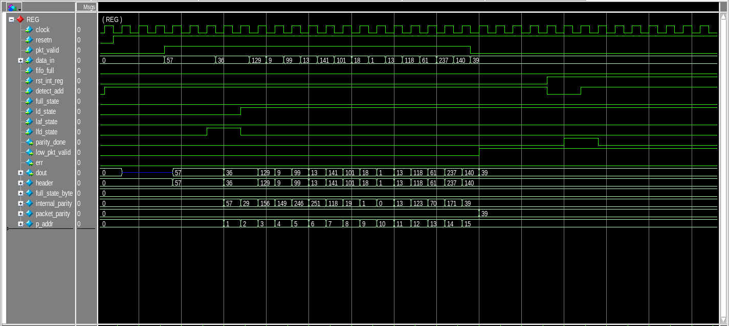
Register
Port Listing for Refister:
| Port | Type |
|---|---|
| clock | input |
| resetn | input |
| pkt_valid | input |
| data_in | input |
| fifo_full | input |
| rst_int_re | input |
| detect_add | input |
| full_state | input |
| ld_state | input |
| laf_state | input |
| lfd_state | input |
| parity_done | output |
| low_pkt_valid | output |
| err | output |
| dout | output |
List of ports for Router Register
Block Diagram for Register
\newpage
Timing Analysis for Register
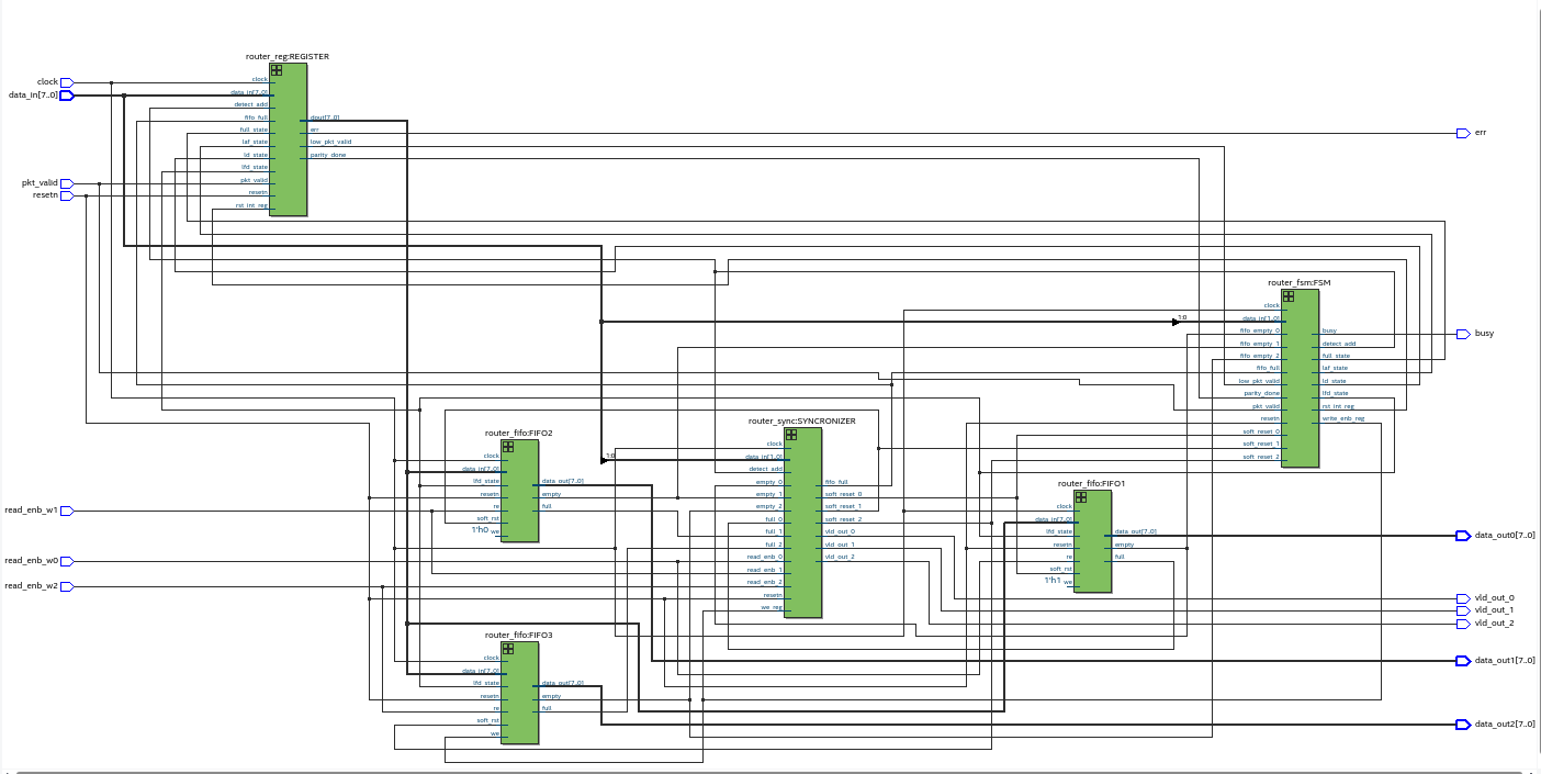
Router Top
Port Listing for Router Top:
| Port | Type | Descriopion |
|---|---|---|
| clock | input | Clock signal |
| resetn | input | Active low reset |
| pkt_valid | input | Packet valid signal |
| data_in | input | 8-bit Input data |
| read_enbw | input | read enable pin |
| data_out0 | output | 8-bit data of FIFO-1 |
| data_out1 | output | 8-bit data of FIFO-2 |
| data_out2 | output | 8-bit data of FIFO-3 |
| busy | output | busy signal |
| err | output | error signal |
| vld_out_0 | output | valid out for FIFO-1 |
| vld_out_1 | output | valid out for FIFO-2 |
| vld_out_2 | output | valid out for FIFO-3 |
: List of ports for Router Top
Block Diagram for Router Top
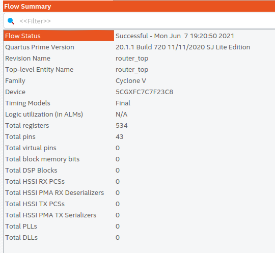
Outputs:
Flow Summary
\newpage
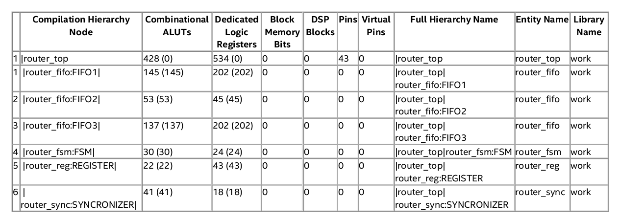
Analysis & Synthesis Resource Usage Summary:
\newpage
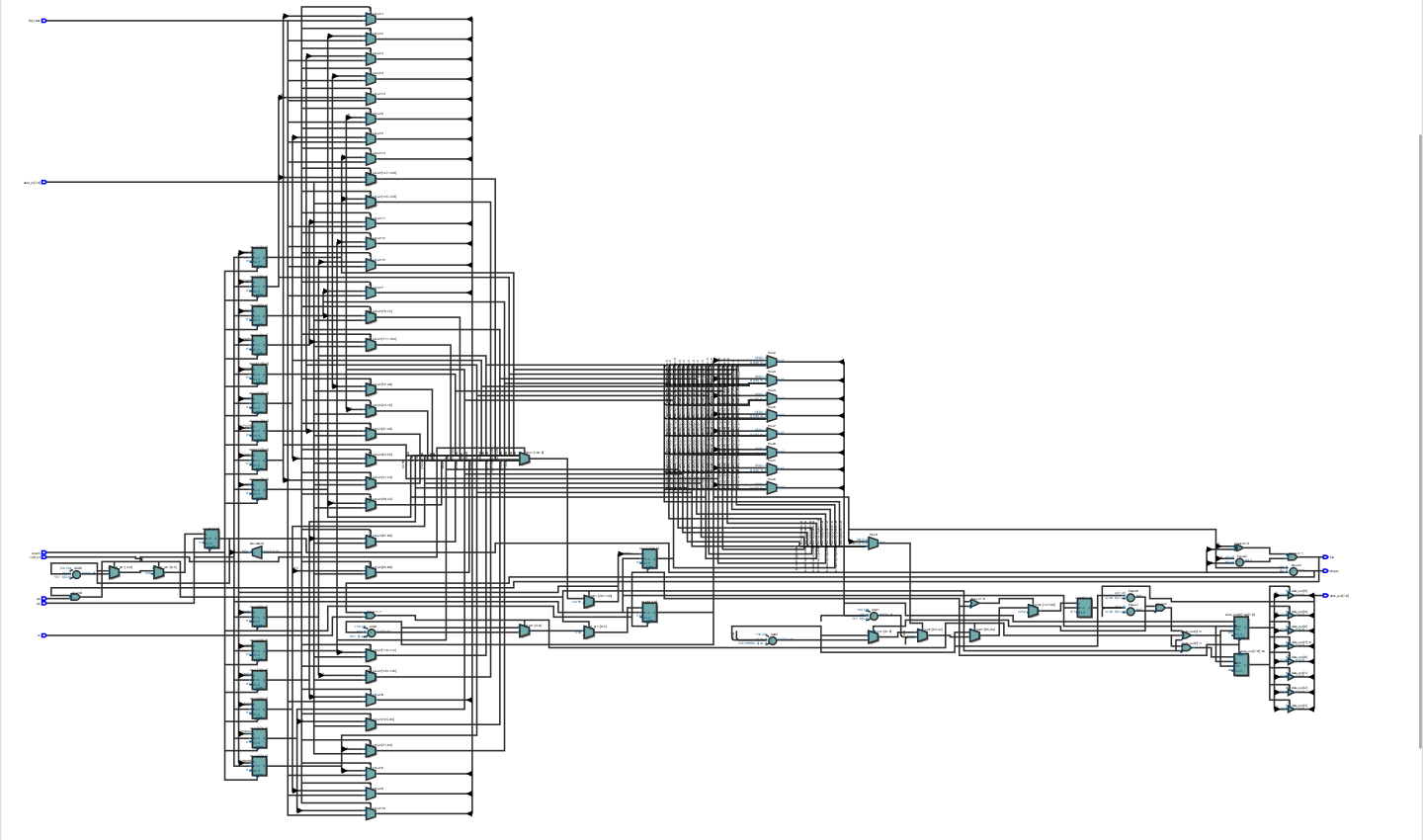
Post-Synthesis Netlist for Top Partition

\newpage
Timing Analysis for Router Top
- We shall be sending a data of 16 bytes and verify then receive it from FIFO-1. Also, I have disabled other two FIFO for this case.
- Router Top Timing Analysis
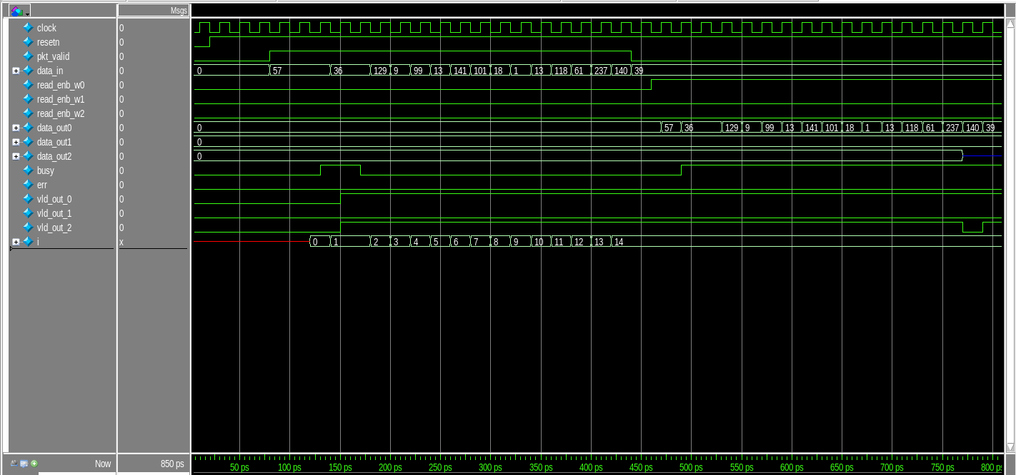
Router Top DUT
- We can see that FIFO-1 has faithfully reproduced the input data to the output.
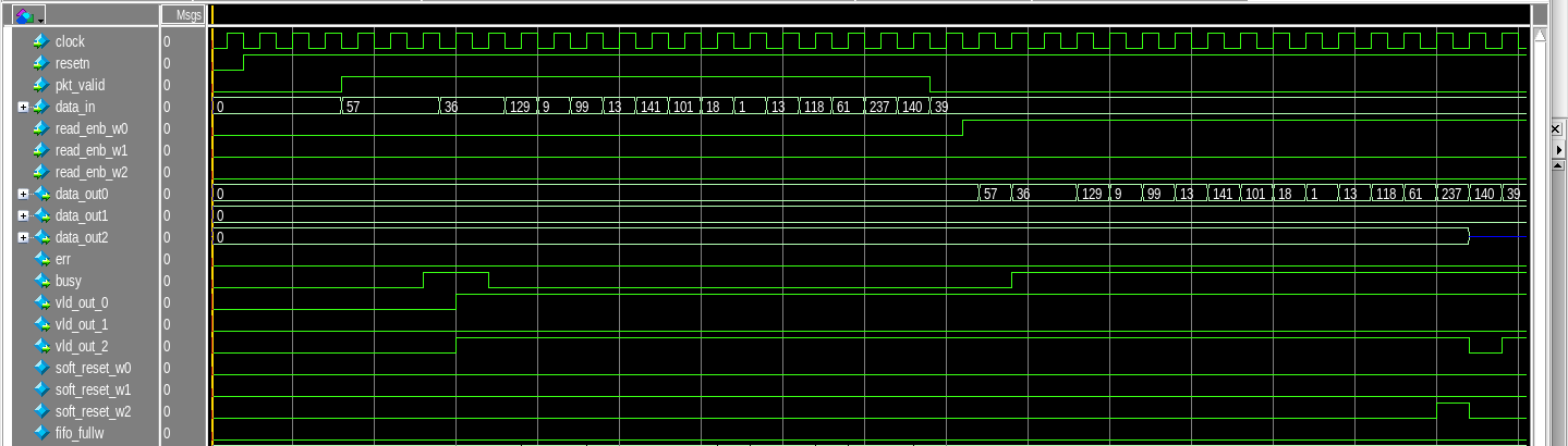
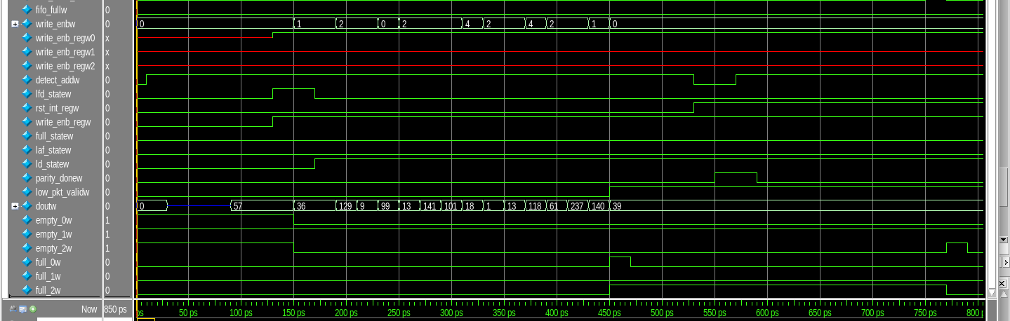
Conclusion: The router is simulated and synthesized successfully.
>> User_Feedback_Loop
<!DOCTYPE html>
module Steps to Implement a 3-bit Wallace Tree Multiplier using SKY130 PDK and eSim ();
A Wallace multiplier is a digital circuit which multiplies two integers in binary format. It uses half and full adders to sum partial products in stages until two numbers are left. In this project I shall be developing a 3-bit multiplier using Wallace tree reduction. Before you go through this make you have the sky130pdk in this folder and change the current path in “wallace3tree_test.cir” directing to the sky130 pdk.
Requirements
- NGSpice Software
- eSim
Ports of CMOS 3-bit Wallace Multiplier

| Port | Type | Description |
|---|---|---|
| a | Input | 3-bit input |
| b | Input | 3-bit input |
| z | Output | 6-bit output |
| Here “a” and “b” are 3-bit input digits, and the output “z” contains 6-bits. |
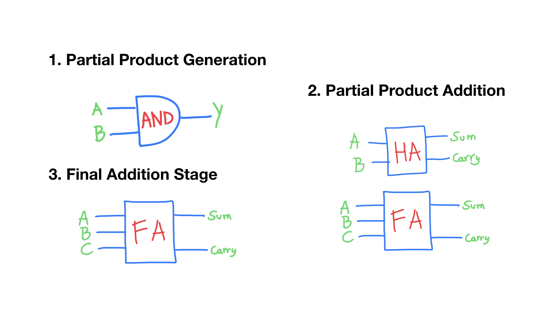
Components of 3-bit Wallace Tree Multiplier
| Component | Total |
|---|---|
| AND gates | 9 nos |
| Half Adders | 3 nos |
| Full Adders | 3 nos |
Sub-Circuits
- halfadder
- fulladder
- and_gate
- xor_gate
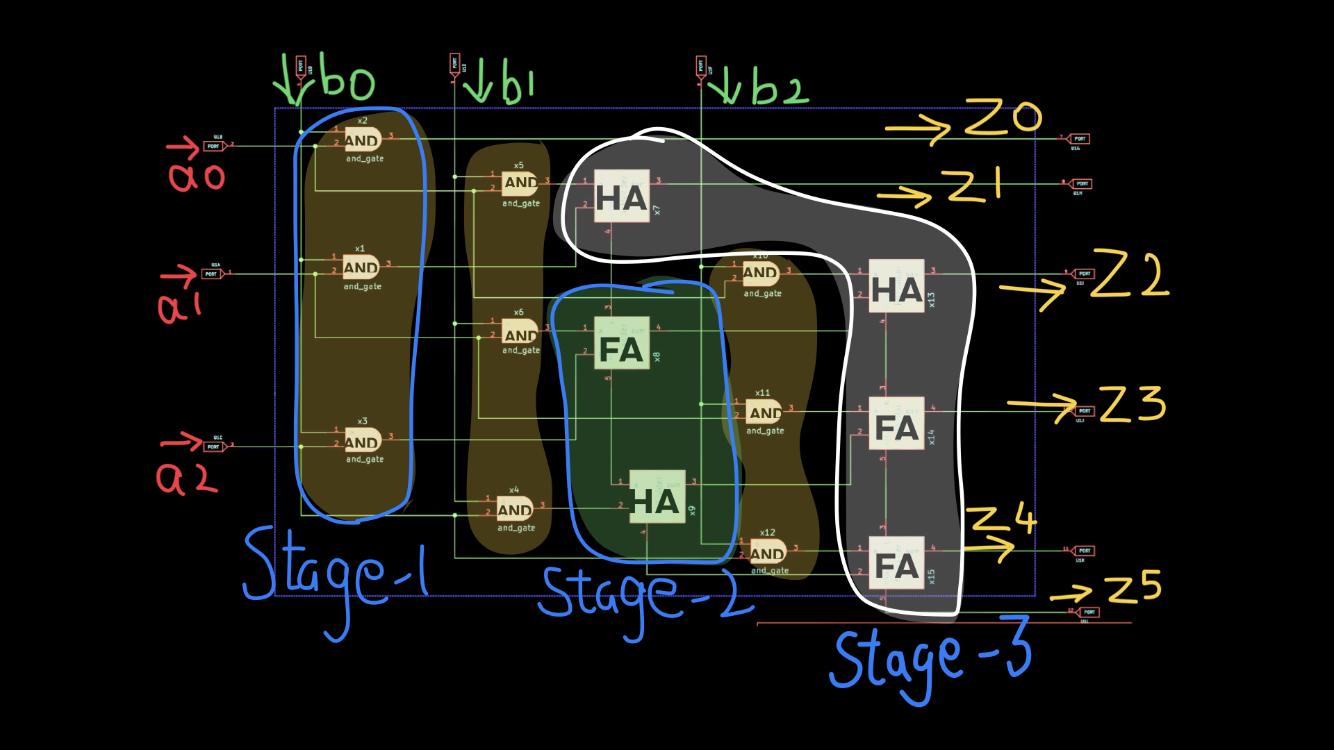
Wallace Tree Algorithm
It has three steps:
- Multiply each bit of one of the arguments, by each bit of the other.
- Reduce the number of partial products to two by layers of full and half adders.
- Group the wires in two numbers, and add them with a conventional adder.
3 bit Reduction algorithm

Schematics
You can view the schematic using esim software, launch esim and
open this folder, the esim automatically detects the .proj file
and creats a project for “wallace3tree”. Then select respective
“.sch” file to launch the schematic of the project.
Steps To Run Project:
Step-1: Downloading the repository
$ git clone https://github.com/Ikarthikmb/wallace-tree.git
Step-2: Creating eSim Project
Open eSim application and select open project then navigate to folder wallace-tree
to select wallace3tree. The wallace3tree project file is now added in the eSim.
Step-3: AND gate

AND gate schematic
Draw a schematic with eSim Schematic editor for an AND gate logic circuit with cmos logic, perform CRC error check and export the ngspice netlist.
Step-4: XOR gate

Draw a schematic with eSim Schematic editor for an XOR gate logic circuit with cmos logic, perform CRC error check and export the ngspice netlist.
Step-5: Half Adder

Draw a schematic with eSim Schematic editor for an Half Adder circuit with AND and XOR gates, then perform CRC error check and export the ngspice netlist.
Step-6: Full Adder

Draw a schematic with eSim Schematic editor for a Full Adder circuit with AND and XOR gates, then perform CRC error check and export the ngspice netlist.
Step-7: 3-bit Wallace tree Multiplier
Draw a schematic with eSim Schematic editor for a 3-bit Wallace Multiplier logic circuit with AND gates, half adders and full adders. Then perform CRC error check and export the ngspice netlist.
Step-8: Convert KiCAD to NGSpice
After the netlist is generated, select kicad to spice from the eSim window to convert the
kicad schematic to ngspice model. Rename the netlist file wallace3tree.cir.out to wallace3tree_test.cir
$ cp wallace3tree.cir.out wallace3tree_test.cir
Step-9: SKY130 Tech
Add the path for the sky130pdk in the wallace3tree.cir.out file. In the subcircuit .sub file replace the
model mosfet_n with sky130_fd_pr__nfet_01v8 and mosfet_p with sky130_fd_pr__pfet_01v8.
Now, lets simulate the circuit with ngspice.
Step-10: NGSpice Simulation

Lets assign the inputs a and b with the pulse signals and try to observe the output.
$ ngspice wallace3tree_test.cir
With this the ciruit simluation is verified. If you encounter with errors recheck the circuit and perform the run again.
Video Tutorial
References:
- Wallace Tree: https://en.wikipedia.org/wiki/Wallace_tree
- eSim EDA tool: https://esim.fossee.in
This is a project submitted to eSim marathon partnered with Free/Libre and Open Source Software for Education(fossee), Indian Institute of Technology, Bombay(IITB), VLSI System Design(VSD) and Ministry of Education, India during May-June of 2021.
>> User_Feedback_Loop
), blog, and let’s connect