rtl_designs
8-bit Numerically Controlled Oscillator
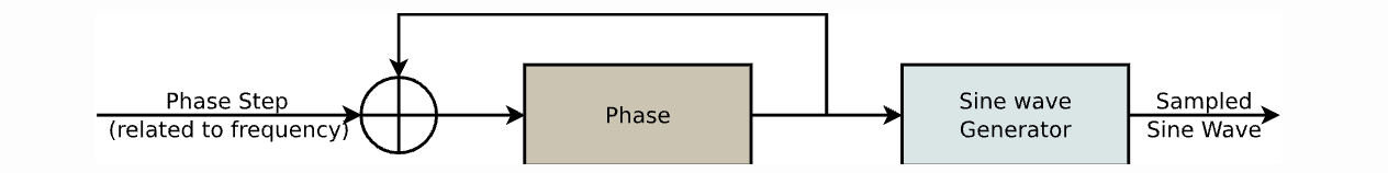
This RTL module implements a simple 8-bit Numerically Controlled Oscillator (NCO). The NCO can be used to generate sine and cosine waves at a programmable frequency.
Pinout
| Name | Type | Length | Description |
|---|---|---|---|
| clk | input | 1 bit | Clock signal |
| reset | input | 1 bit | Asynchronous reset signal |
| phase_inc | input | 8 bits | Phase increment value. This value determines the frequency of the generated waveform. |
| sine_out | output | 8 bits | Sine wave output |
| cosine_out | output | 8 bits | Cosine wave output |
- Compile using Icarus Verilog
iverilog -o nco_tb.out nco_tb.v nco.v
vvp nco_tb.out
- To view the waveform use GTKwave viewer. Once you have the tool installed you can trigger it using the following command
gtkwave nco_tb.vcd
The phase_inc value determines the frequency of the generated waveform. A higher phase_inc value will result in a higher frequency waveform. The following table shows the relationship between the phase_inc value and the frequency of the generated waveform:
| phase_inc | Frequency (Hz) |
|---|---|
| 1 | clk / 256 |
| 2 | clk / 128 |
| 4 | clk / 64 |
| 8 | clk / 32 |
| 16 | clk / 16 |
| 32 | clk / 8 |
| 64 | clk / 4 |
| 128 | clk / 2 |
| 256 | clk |
Example
The following example shows how to use the NCO module to generate a 1 kHz sine wave:
assign phase_inc = 8'h01; // clk / 256
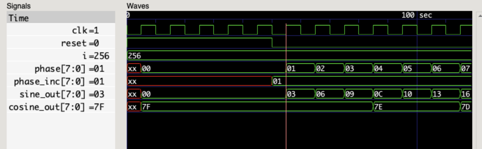
Output Waveform