rtl_designs
PWM Generator
Problem: PWM (Pulse Width Modulation) Generator
Design a PWM generator module in Verilog. The PWM generator should take a duty cycle percentage as input and generate a PWM signal with a configurable frequency.
Steps to Run
Compile the verilog module
% iverilog pwm.v
Now compile testbench module
% iverilog tb_pwm.v
% vvp a.out
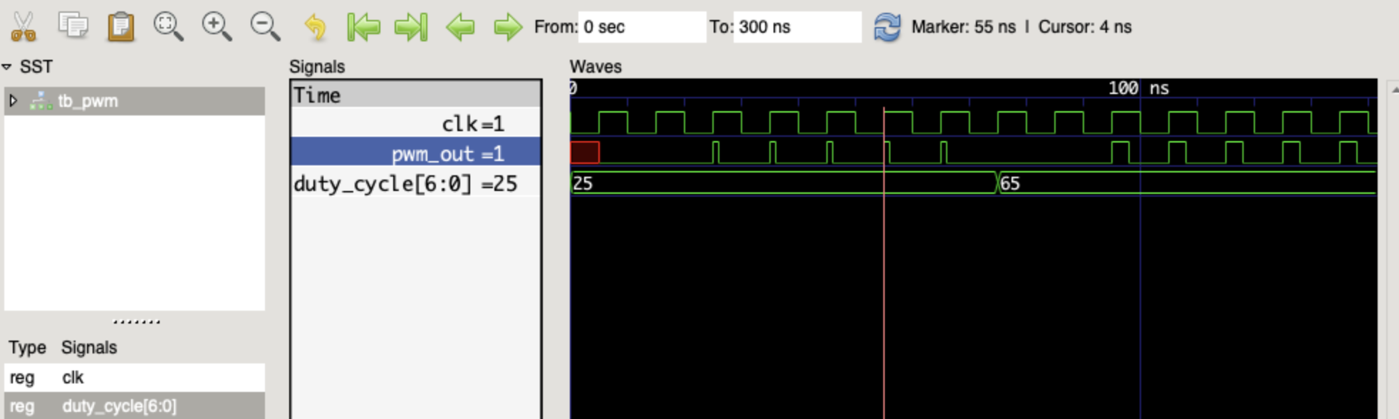
Use the following to view the waveforms in GTKwave
% gtkwave tb_pwm.vcd
Requirements:
The PWM generator should have the following input ports:
clk: Clock input rst: Reset input (active high) duty_cycle: Duty cycle percentage input (0 to 100, where 0 represents 0% and 100 represents 100% duty cycle). frequency: Frequency input to set the PWM signal frequency. The PWM generator should have the following output port:
pwm_out: PWM output signal. The module should generate a PWM signal with a duty cycle as specified by the duty_cycle input.
The frequency of the PWM signal should be adjustable using the frequency input.
The duty cycle should be updated synchronously with the clock signal.
The PWM signal should have a 50% duty cycle when the duty_cycle input is 50%.
The module should be synthesizable and testable.
Optional Task:
Implement multiple PWM channels with individual duty cycle and frequency settings.
Applications: PWM is commonly used for controlling the intensity of LEDs, the speed of motors, and other applications where analog-like control is needed with a digital signal.